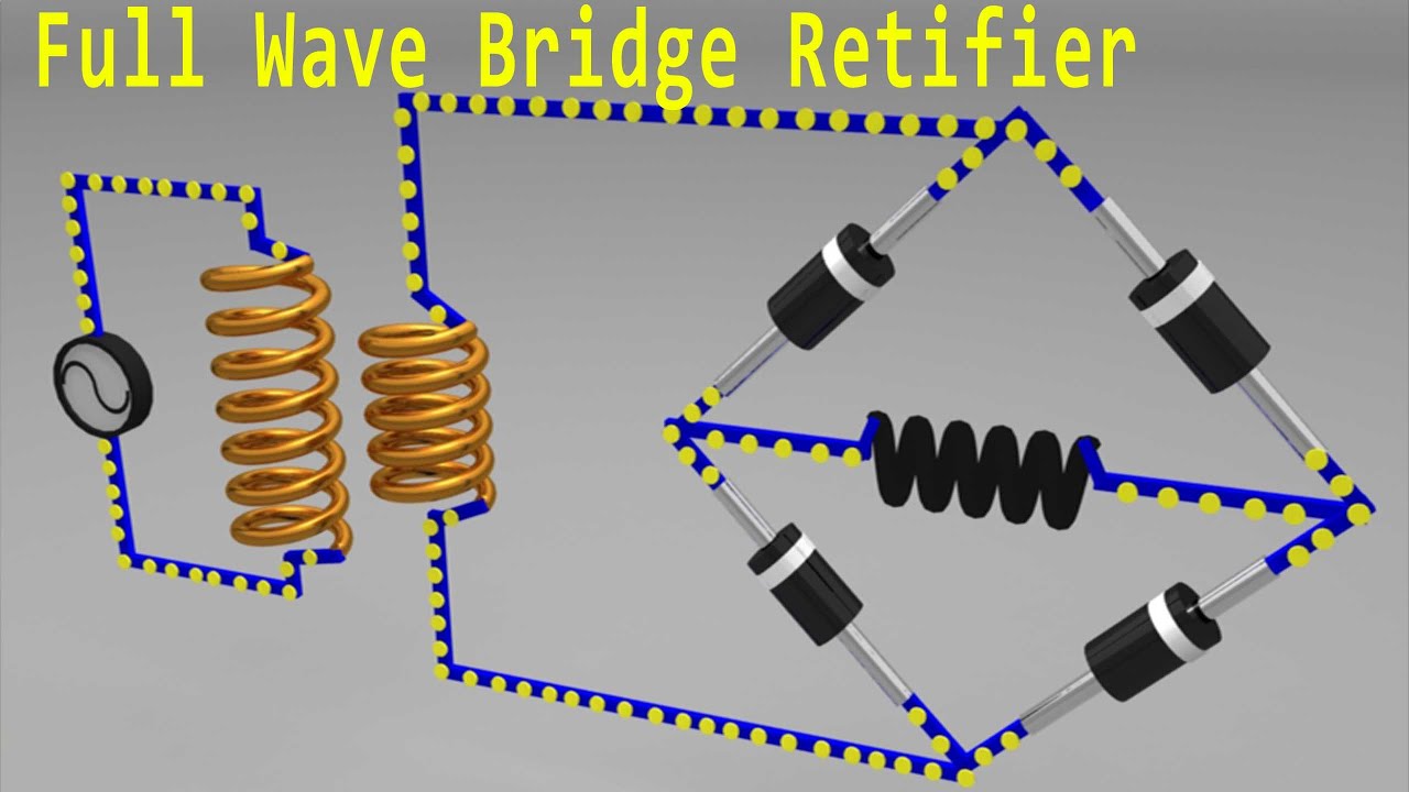
Bridge Wave Rectifier Circuit Diagram
Full wave rectifier-bridge rectifier-circuit diagram with design & theory Rectifier bridge wave circuit diagram regulator ic Full wave bridge rectifier circuit diagram
8: Three-phase full-wave bridge rectifier circuit | Download Scientific
Full wave bridge rectifier Rectifier bridge wave circuit diagram diode voltage operation peak fig shown value inverse secondary its negative below Rectifier wave circuit filter without bridge diagram capacitor tapped diodes center type circuits four board below using circuitdigest electronic choose
Rectifier circuit diagram
Full wave bridge rectifierRectifier wave bridge operation half animation input working cycle current positive forward during gif diodes tutorial reverse biased d3 d4 Rectifier wave bridge circuitFull wave rectifier circuit diagram (center tapped & bridge rectifier).
Rectifier circuit bridge diagram wave working detailsFunction of resistor in full wave rectifier Rectifier wave current bridge path circuit diagram half cycle flow 2ndRectifier bridge wave supply micro diagram digital detail.

Rectifier bridge
Schematic diagram of full-wave bridge rectifier.Rectifier bridge diagram circuit wave construction principle working 8: three-phase full-wave bridge rectifier circuitFull wave bridge rectifier operation.
Full wave bridge rectifierFull wave bridge rectifier supply Full wave bridge rectifier circuit diagramRectifier circuit diagram wave output waveform input.

What should i consider when choosing the right diode…
Rectifier bridge workingRectifier bridge wave animation circuit diagram physics electronics Rectifier diode rectifiers circuitsBridge wave rectifier circuit output half diagram cycle principle working rectifiers input theory current.
Full wave rectifier-bridge rectifier-circuit diagram with design & theoryRectifier wave bridge circuit diodes operation negative forward becomes its figure below biased Full wave bridge rectifier – circuit diagram and working principleFull wave bridge rectifier.

Full wave bridge rectifier – circuit diagram and working principle
Rectifier wave bridge circuit operation contents its disadvantages advantagesRectifier circuit diagram Rectifier transformer waveform tapped etechnog.
.


